Second Balancing Bot -- Rock Solid
What I Was Building
The whole project was an excuse to try out brushless DC motors — specifically gimbal motors — and fix everything that frustrated me about the first balancing bot.
The first one balanced, but barely. It jittered and clicked and was never quite stable. The culprit was the brushed DC motors and their deadband. So this time: BLDCs, a better chassis, a proper power source, and joystick control.
The Main Choices
Motors: Gimbal motors. Not the fastest, but the right size, gearbox-free, and enough torque to drive the wheels directly. Running them with SimpleFOC controllers meant I had smooth, precise field-oriented control — no deadband, no cogging, just clean torque.
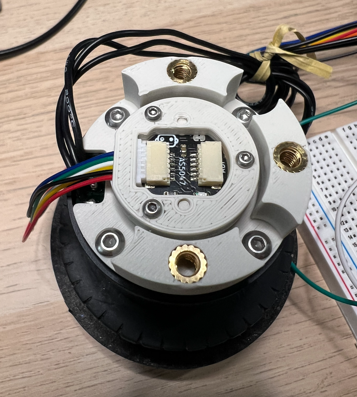
Encoder: Before I could use the motors, I had to mount an AS5047P magnetic encoder (14-bit resolution) to the back of each one and design a 3D printed bracket to hold it in place. Then attach a small diametrically magnetized magnet to the motor shaft. The sensor+magnet gives feedback to the FOC controller about what angle and speed the wheel is currently at.
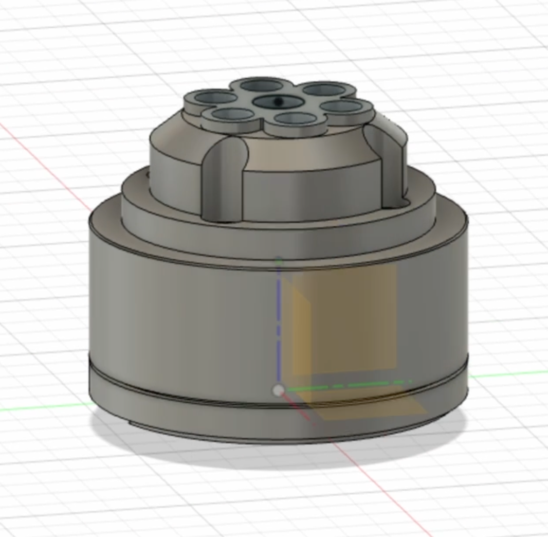
Wheels: I pillaged my Lego collection for wheels, then designed and printed custom hubs to connect them to the BLDC shafts. Free wheels, and they look great.
Power: Makita 18v lithium-ion battery with a "power wheels adapter". This was a big breakthrough for me not having to use a sketchy-looking homemade battery I used in the first balancing bot. I live in a condo and the thought of a battery fire sends chills down my spine. Having a durable battery that you can drop and toss around a room and it already has a charger and a well tuned BMS is a load off my mind.
The 18v Makita batteries were both the "dumbest" (ie. no data pins or fancy signal to draw power) and they were the right form factor, so I went with those. I've read fancier brand batteries like Milwaukee might take more work to draw power from, but I'm not sure
I placed the battery near the top of the chassis intentionally — a top-heavy robot is actually easier to balance because the center of mass is higher, giving the controller more time to react
Control: A joystick mixed into the balance loop. The balancing robot's setpoint isn't 0° — it's whatever angle corresponds to "moving at the speed the joystick is asking for." That means balancing and driving are the same controller, just with a shifted target.
The Chassis
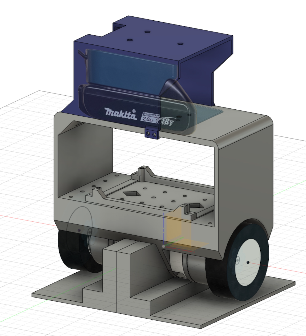
One of the lessons from the first bot was how much time gets wasted assembling and reassembling a modular chassis. So this time I designed the entire frame as a single printed piece. Other than the battery compartment on top, the whole thing comes off the printer ready to use. No bolting sub-assemblies together. No alignment headaches.
I was proud of that.
The Result
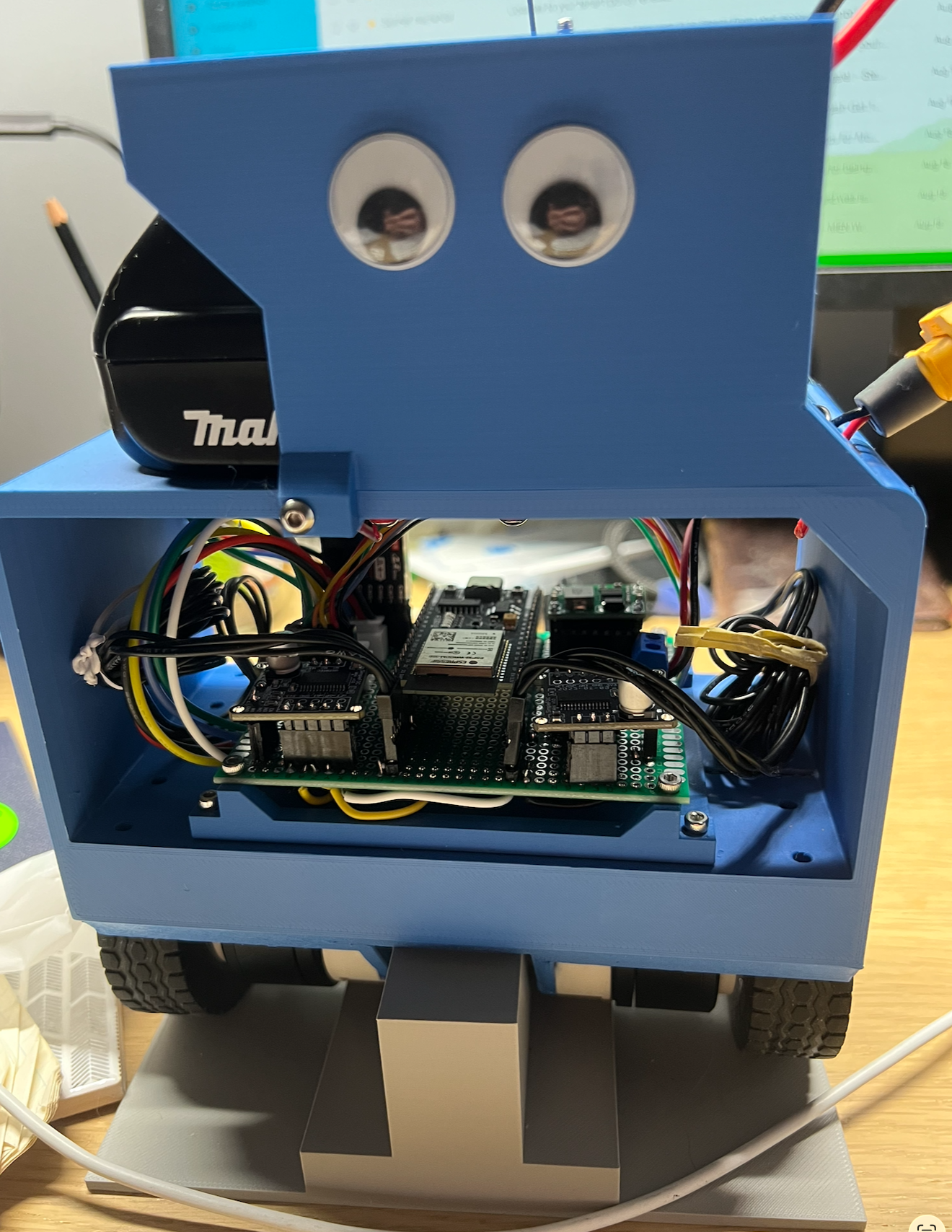
This thing was rock solid.
I could almost slap it and it would stay steady and upright. The difference from the first bot was immediate and obvious. The BLDCs respond so fast that the PID controller barely has to work — by the time an error builds up, the correction is already happening.
Strong signal that these super-responsive brushless motors are the right approach for balancing robots. More work to set up, big payoff.
The Annoying Parts
Perfboard. I connected all the electronics on perfboard and soldered everything by hand. That took most of a day and is exactly as tedious as it sounds. One bad joint and you're hunting through a rats nest of wires. Next time I'll design a custom PCB and order it. Cleaner, more reliable, and honestly less total work once you factor in the debugging time.
Heat. The gimbal motors got warm after extended running. They're not optimized for continuous load — they're designed for camera stabilizers, not robots. Good enough for a prototype and a useful data point, but I'd want to look at proper pancake BLDCs for a next version.
What's Next
The most ambitious project to date -- Robot Dog